Posts

Showing posts from February, 2021

SUB MODULE 7.3: TWIST DRILLS
Image
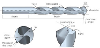
EASA PART 66 MODULE 7 MAINTENANCE PRACTICES SUB MODULE 7.3 Twist Drills: Twist drill is a cutting tool comprised of cutting point at tip of a shaft with helical cutting edge. While the range of tools, designed to create holes in metals and other materials is vast, the Morse-type (named after its inventor, an American engineer) of Twist Drill (refer to Fig. 3.13) is the one most commonly used in aircraft (and in general) engineering. The shank is the part of the twist drill that is gripped and driven by the chuck of the drilling machine and it is on the shank that the details of the type (grade) and diameter of the drill can usually be found printed or engraved. On drills up to 12.5 mm (½”) diameter, the shank is parallel and placed into the jaws of a self-centring chuck. On drills above 12.5 mm the shank is usually tapered (to a Morse Taper) of 1:20. The tapered shank fits directly into a matching tapered housing in the drilling machine spindle. The tapered shank usually ends in a tan

Sub Module 7.3: Twist Drill (MCQ)

  EASA MODULE 7A Sub Module 7.3 TOOLS TWIST DRILL ( MCQs): Loading…  

Sub Module 7.3 Files (ESSAY)

Image
  EASA MODULE 7A Sub Module 7.3 TOOLS Files   Files are cutting tools for removing metal from a surface and are made of high-carbon steel. The blade is hardened, whilst the tang (to which, a handle must always be attached, for safety reasons, before the file is used), is left in a softer, tougher condition and is, therefore, less brittle. Hand files are classified by their:  Length  Shape  Cross-Section  Cut  Grade The length of a file is measured from the shoulder to the tip of the blade. Files are available, for special work, in lengths from 75 mm (3 in) to 350 mm (14 in). The most common sizes are 150 mm (6 in), 200 mm (8 in) and 250 mm (10 in). Files are available in a variety of shapes (refer to Fig. 3.9), and the most common shapes are those which are:  Tapered  Parallel  Bellied       Shapes of Files The various shapes and the cross-sections of files allow them to be used on a wide range of tasks. The standard file cross sections are:  Hand (Flat)  Round (Circular)  Half-Round  

Sub Module 7.3: Files (MCQ)

  EASA MODULE 7A Sub Module 7.3 TOOLS FILES (MCQs) : Loading…  

Sub Module 7.3 Tools (MCQ 1)

EASA MODULE 7 SUB MODULE 7.3 TOOLS Loading…  

Sub Module7.5: Engineering Drawings (MCQ)

EASA MODULE 7 SUB MODULE 7.5 ENGINEERING DRAWINGS Loading…  

Sub Module 7.3: Filing Techniques (ESSAY)

Image
EASA MODULE 7A Sub Module 7.3 TOOLS Filing Techniques:   Good filing is not just a matter of removing surplus metal. The correct amount of material, at each point on the surface of the work piece, needs to be removed, so that the dimensions and tolerances, set by the drawing, will be met. Proficiency comes with practice. New files should, if possible, be first used on soft metal. This achieves ‘tempering’ of the cutting teeth and will contribute to a longer life for the file. Before starting work, it must be ensured that the work piece is secure and correctly placed, as both hands are required for filing tasks. A file must never be used without a handle. The file will not be under full control and the risk of puncturing the wrist or palm is very great.   Files must be handled carefully. File blades, being hard, are also brittle and will break if dropped. After use, all files should be returned to their respective racks or bandolier-type holdalls, to prevent them knocking together and b

Sub module 7.17: De-icing/Anti-icing of Aircraft

Image
EASA MODULE 7A Sub Module 7.17 AIRCRAFT HANDLING AND STORAGE DE-ICING/ANTI-ICING OF AIRCRAFT     Ice Types There are three main types of ice/frost that can affect an aircraft’s performance, Hoar Frost, Rime Ice and Glaze Ice. The temperature and weather conditions will determine the type of ice that forms, but all three types can have a detrimental effect. The Dew Point is the temperature at which moist air becomes saturated and deposits dew if in contact with a colder surface or the ground. Above ground, condensation into water droplets takes place. Hoar Frost is a deposit of ice crystals that form on an objectwhen the dew point is below freezing point. High humidity will normally produce hoar frost, as these are similar to conditions that produce dew. Hoar frost can form when the air temperature is greater than 0°C, but the aircraft skin temperature is less than 0°C. This type of frost produces a very rough surface which leads to turbulent airflow. Rime Ice is a light coloured o

Sub Module 7.17: Fueling of Aircraft

Image
EASA  MODULE 7A Sub Module 7.17 AIRCRAFT HANDLING AND STORAGE AIRCRAFT FUELING PROCEDURES The use of the term ‘fueling’ can include both refueling and defueling procedures and these notes contain examples of the essential points to be considered when refueling and defueling aircraft. There may, however, be some further, local instructions, regarding the responsibilities of the various personnel involved in fueling procedures and these will always take precedence in conjunction with the relevant Maintenance Manual. Refueling When refueling the AMM should always be consulted so that the positions and capacities of the fuel tanks and also the type of fuel, position of the refuelling point(s) and refuelling procedures are known. There are two general re-fuelling methods: 1. Gravity or over-wing refuelling: which is, essentially, the same method as used to refuel a motor car (automobile), with a similar type of refuelling hose being used. As the name suggests, the filler points are, general

Sub Module 7.3: Hammers

Image
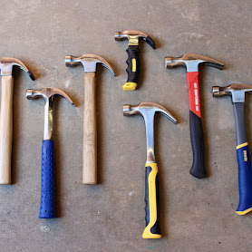
  EASA MODULE 7A Sub Module 7.3 TOOLS HAMMERS: Hammers are classified by their weight and type of head. Steel heads are forged and manufactured from high-carbon steel. Most shafts are made from straight-grained Ash or Hickory and are secured to the head by wedging. The main types of engineering hammers are : Ball Pein: The flat surface is used for most general-purpose work whilst the ball pein is used primarily for riveting-type operations.       Straight Pein: Used for general work, the narrow, straight pein being particularly suitable for use where access to the work is limited. Cross Pein : As for the straight pein, but the axis of the pein is at 90° to that of the shaft. Hide/Copper Face: The rawhide facing enables heavy blows to be delivered without damaging the surface of the work, while the copper face may be used for heavier types of work than hide faced hammers .   Rubber Head and Plastic Face: More modern versions of the Hide Face hammer. Can often have one of each type o

Sub Module 7.17: Aircraft Jacking

Image
      EASA MODULE 7A Sub Module 7.17 AIRCRAFT HANDLING AND STORAGE    AIRCRAFT JACKING: Aircraft may need to be jacked for a variety of purposes. These may include component changes, retraction tests, weighing of the aircraft and aircraft rigging checks. Care needs to be taken when jacking, to avoid damage to aircraft or equipment. Jacking points are provided in the wings and fuselage, at strong points, to enable the whole aircraft to be lifted, and there are, usually, other points, at the nose and main undercarriages, to enable individual wheels to be changed. Some aircraft require a jacking pad to be fitted to each jacking point, while in some, the jacking pads are built into the structure. Special jacking adapters and beams may be available to lift individual axles.   In all instances, the Maintenance Manual should be consulted, so that the correct equipment and procedures may be used. Because of the position of the jacking points, the C.G. of some aircraft may be well behind, or in

Sub Module 7.17 Aircraft Handling and Storage

Image
EASA MODULE 7A Sub Module 7.17 AIRCRAFT HANDLING AND STORAGE     AIRCRAFT TAXIING AND TOWING:      Aircraft need to be moved on the ground, between flights, for a variety of reasons, which can include:  Moving aircraft into, or within hangars for maintenance  Re-positioning aircraft for ground running or storm protection  Emergency removal of aircraft from a taxi-way.   It is important that the aircraft be moved safely, using the correct equipment, to avoid injury to personnel or damage to aircraft. Small aircraft, generally require little preparation but, with larger aircraft, some or all of the following points may be relevant: Preparation for the reception of the aircraft should be made in advance of its arrival. There should be adequate space available for the aircraft, with consideration given, as appropriate, to clearances for jacking, access for cranes etc. All equipment required for servicing should be available and serviceable. The aircraft should be in a satisfactory condit

Sub Module 7.19 : ABNORMAL EVENTS (ESSAY QUESTION)

Image
LIGHTNING STRIKES   Lightning is the discharge of electricity in the atmosphere, usually between highly charged cloud formations, or between a charged cloud and the ground. If an aircraft is flying in the vicinity of the discharge or it is on the ground, the lightning may strike the aircraft. This will result in very high voltages and currents passing through the structure.     Effects of a Lightning Strike:   Lightning strikes are likely to have two main effects on the aircraft 1: Strike damage where the discharge enters the aircraft. This will normally be on the extremities of the aircraft, the wing tips, nose cone and tail cone and on the leading edge of the wings and tail plane. The damage will usually be in the form of small circular holes, usually in clusters, and accompanied by burning or discoloration. 2:  Static discharge damage at the wing tips, trailing edges and antenna. The damage will be in the form of local pitting and burning. Bonding strips and static wicks may als

Sub Module 7.16: Aircraft Weight And Balance

Image
EASA MODULE 7 : MAINTENACE PRACTICES SUB MODULE: 7.16 AIRCRAFT WEIGHT AND BALANCE When an aircraft is designed, limits are put on its maximum weight, and restrictions are set up regarding the range within which the center of this weight is allowed to vary. A part of the certification procedure for an airplane is to determine that its weight and balance are within the allowable limits, and this information is furnished with the aircraft as part of its operations manual. Lets check your knowledge about the aircraft weight and balance. Loading… Please provide your feed back in the comment section below. Thanks and Regards, The Hash Academy Team

Sub Module 7.15: SOLDERING

Image
Soldering: Soldering is a process of joining two metals without melting them. Soldering differs from welding in that it is done at considerably lower temperatures so that the parent metals do not melt and fuse together. Instead, a fusible and, usually, non-ferrous alloy (with a lower melting point) is applied between the heated metals of the joint, such that the fusible alloy forms a metallic bond with the parent metals and, on cooling, creates a solid joint. Tinning: Before an iron can be used for soldering, the contact surfaces must be given a coating of tin or solder this process is called “tinning” the iron. Solders: Ordinary soft solder is a fusible alloy consisting chiefly of tin and lead. It is used to join two or more metals at temperatures below their melting point. The standard grades of soft solder are as follows. 1. Tinman's 2. Electrician's 3. Lead Silver The two basic methods of soldering are: 1. Hard Soldering: done at temperatures in excess of 500°C . 2. Soft So